Procedure to calculate the fatigue for each case/member/section.
|
Background:
|
This program was developed to assess fatigue resistance in accordance with Section 11 of AS 4100 of members analysed in Space GASS.
Any individual structural member or welded detail, or a group of members or welded details, can be assessed
for its fatigue strength.
The relevant Detail Category and Capacity factors are selected by the user and are then taken into account within the softwre.
NOT considered are three requirements,
- the Thickness effect in plate thickness greater than 25mm (Section 11.1.7), and
- Shear stress effects
- Limits on stress range of 1.5fy (Section 11.1.4)
|
|
Calculation Procedure:
|
- Parse from the member stress file - for each member, member stastion and loac case - stresses due to Axial loading, N, torsion, Mx, bending about Mz and bending about My
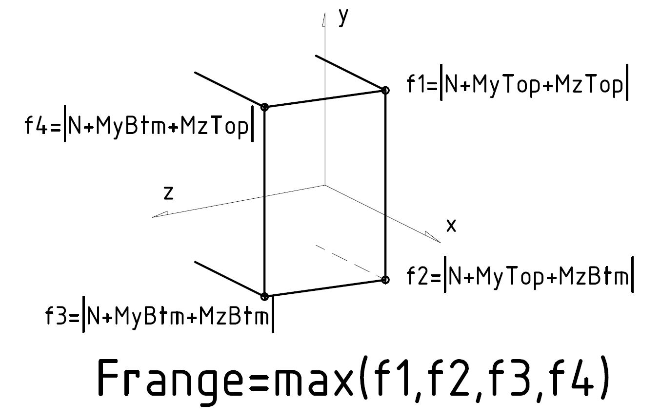
- Evaluate combined stresses at each of 4 extremities of the section, using one of two methods
- Method 1: maxCorner —
- Default method
- Evaluate f1 = |N+MyTop+MzTop|, f2 = |N+MyTop+MzBtm|, f3 = |N+MyBtm+MzBtm|,
and f4 = |N+MyBtm+MzTop|
- Design stress range, Frange is max(f1,f2,f3,f4)
- Method 2: absSum —
- The more conservative method if you are not sure, but non-symmetric sections will be penalised.
- Design stress range, Frange is |N| + max(|MyTop|,|MyBtm|) + max(|MzTop|,|MzBtm|)
- Also check for non-symmetric sections, e.g. Angles, if you should report stress about Principal or Global axes.
- Ask Helmut if you wish to use this method.
- calculate fatigue life, Nsc, for each load case at each station
- Nsc = (frn3×2×106)/(ff/ϕ)3, or
- Nsc = (f55×108)/(ff/ϕ)5
- Fatigue life utilisation (FUL) is calculated at each station as the sum of Caseload cycles/Nsc
- Member FUL is the maximum of all station FUL. The member is at risk if the FUL >1, and has an infinite life it FUL = 0;
- If in any load case combination, a tension only member is disabled, then the calcultion is invalid. Though a ration may be reported, it will be shown formatted in black, rather than in green (pass) or red (fail).
|
|
Hints:
|
|
To generate the report file in Space GASS,
|
- In Space GASS, the analysis must be linear in material properties.
- 2nd order effects can be evaluated non-lineraly.
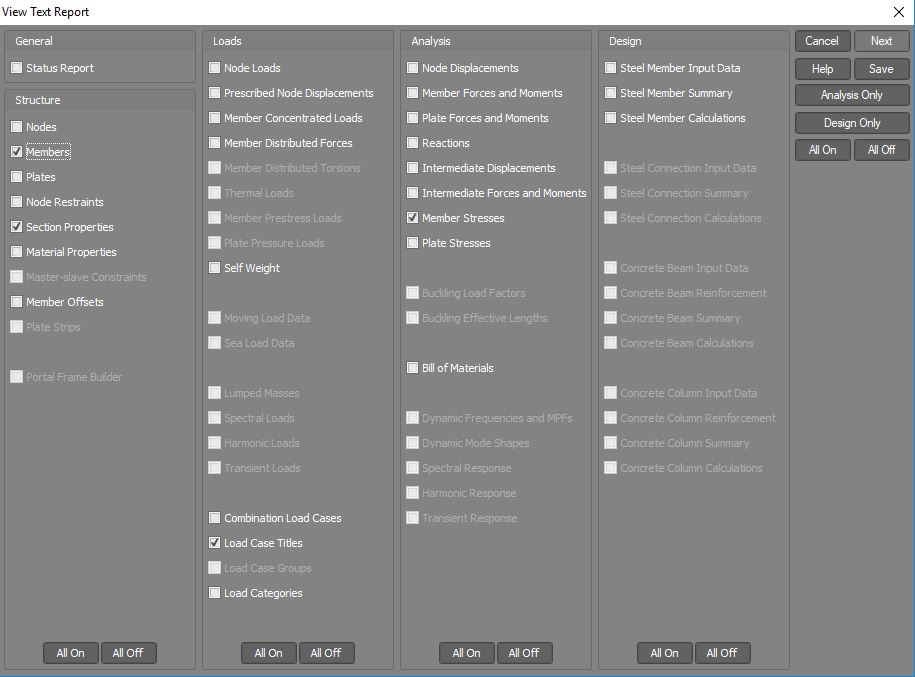
- Generate an analysis report (not design report) as shown in the image below (mouse over to enlarge)
- Consider the number of stations required for the assessment.
Most of the time, fatigue evaluation is only required at the ends of the member, where the welds are.
However, welds and loads may be applied along the member, in which case more station need to be assessed.
|